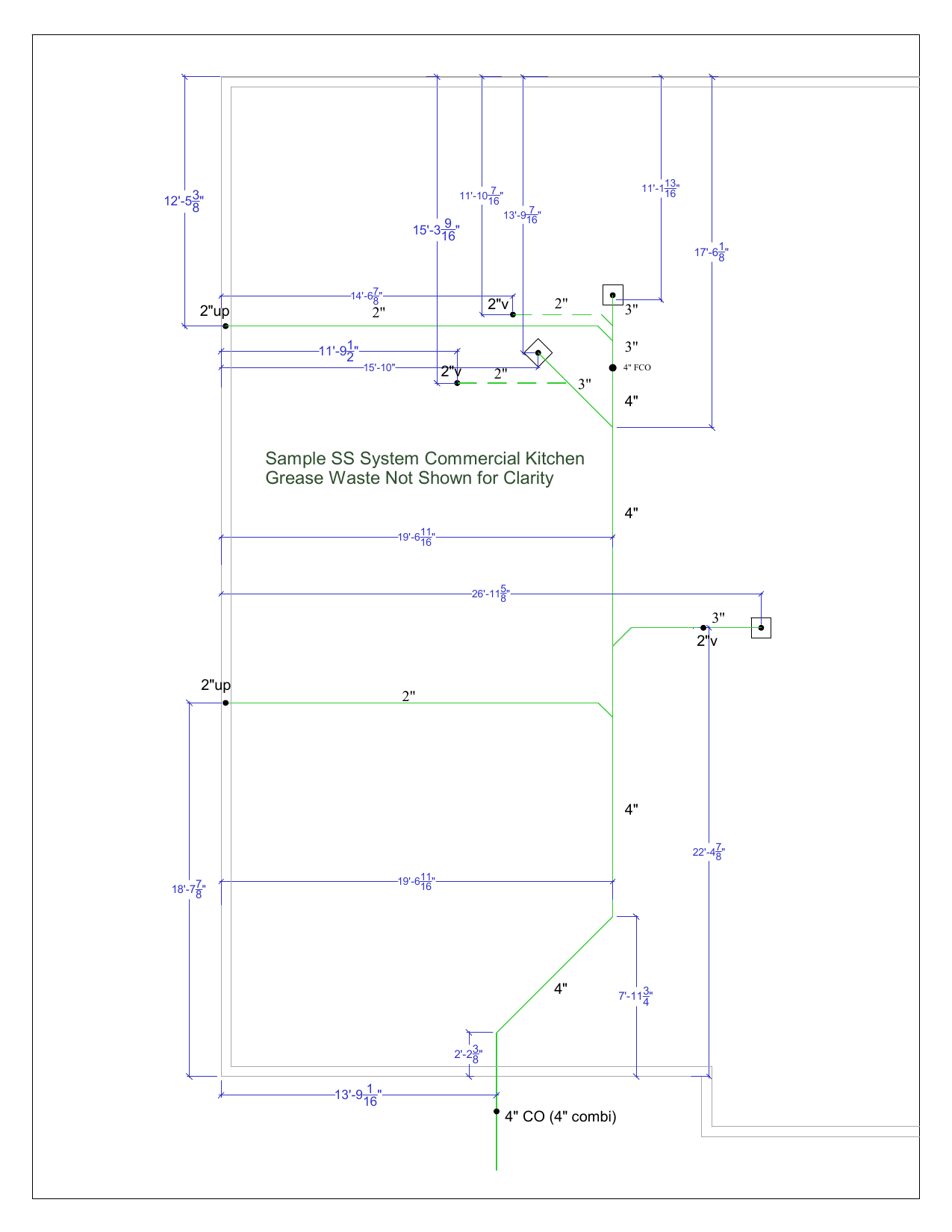
01 / FIELD LAYOUT
Where does everything go?
This layout sample dimensions actual fixture, drain and riser locations from outside building walls so the crew can pull a tape and start locating the work.
Open Full Layout Drawing →These examples show how the layout information and the Pipe Cut Calculator work together. Click any thumbnail or button to open the full PDF in a new tab where you can zoom in.
This layout sample dimensions actual fixture, drain and riser locations from outside building walls so the crew can pull a tape and start locating the work.
Open Full Layout Drawing →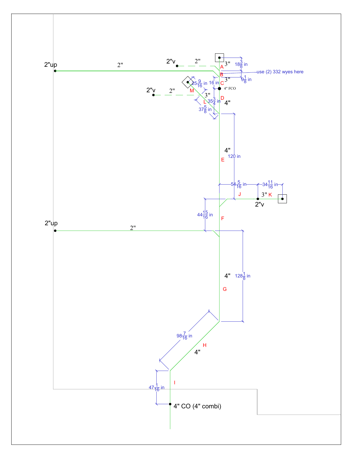
The sample details drawing identifies pipe sizes, fitting relationships, section labels and center-to-center dimensions.
Open Full Details Drawing →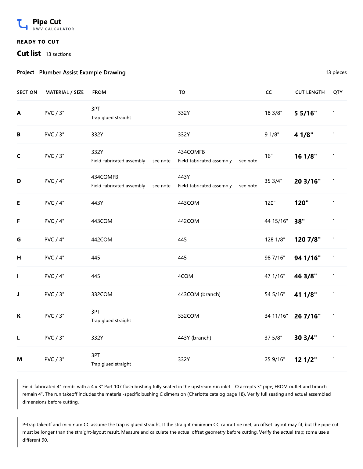
The matching list uses the same section labels and turns the fitting selections and C-C dimensions into clear cut lengths.
Open Full Cut List →Start with the field layout drawing to establish where drains, fixtures and risers belong in the building. Then use the details & C-C dimensions drawing to identify the fitting relationship and center-to-center dimension for each pipe section. Finally, match those sections to the cut list.